Journeyman Shaft Alignment System
Our most popular system and the core building block for an outstanding alignment program!
The most versatile, rugged, and affordable system available. Capable of clamping onto shafts from 1/2" to 200" and shaft to shaft spans up to 34". Variable geometry allows for an infinite number of attachment variations.
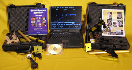
System is comprised of:
- two Standard System sets
- extra extension tube set to span from 9" to 17"
- Shaft Alignment software program (avialable for Windows, OSX, Linux)
- Shaft Alignment Handbook - 3rd Edition
- Anyform magnetic base
- carrying cases
$6995.00 (USD)
How and where is the Journeyman system used?
Well, just about on any type of machinery in virtually any configuration possible. Here's just a few of the infinite number of possible measurement set ups ...
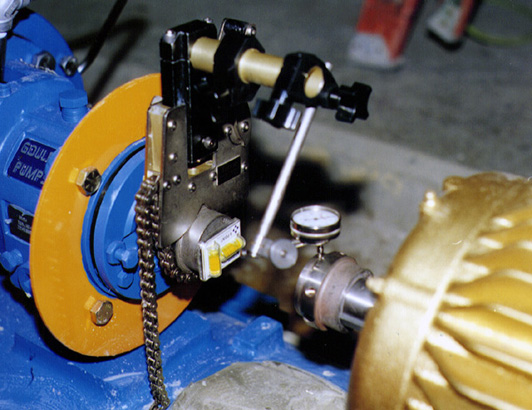
Single bracket capturing measurements directly on a shaft. The brackets are capable of clamping onto a 1/2" diameter shaft. By adding additional roller chain (standrard #35 chain), we've clamped the brackets onto a 200+" diameter shaft!
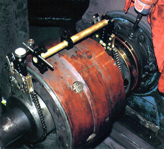
Here, a two bracket arrangement is used where the span bar base on the bracket attached on the left is used as a platform for the dial indicator measurements. When you are performing the reverse indicator method, you capture measurements on one shaft, then remove the span bar and indicator (on the right), remove the span bar base (on the left), slide the span bar base into the bracket on the right, slide the span bar and indicator into the bracket on the left, tighten the six finger clamps, then take the alignment measurements on the shaft on the right without ever removing the bracket clamps!
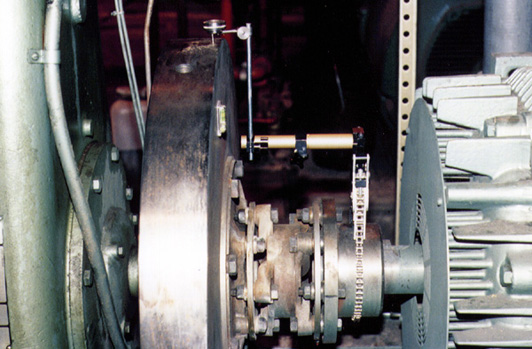
Here the bracket is attached to a motor shaft and the dial indicator is capturing measurements on a flywheel. Since the rod that holds the dial indicator is 5/16", a slightly longer rod was used to reach up a little bit higher.
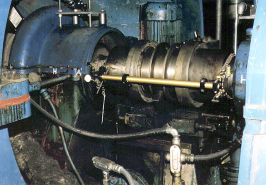
Longer tube sets are also available to span long distances. Here, the span between the steam turbine and the pump is 40".
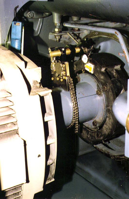
Here the dial indicator is capturing a face reading on the coupling hub of the compressor.
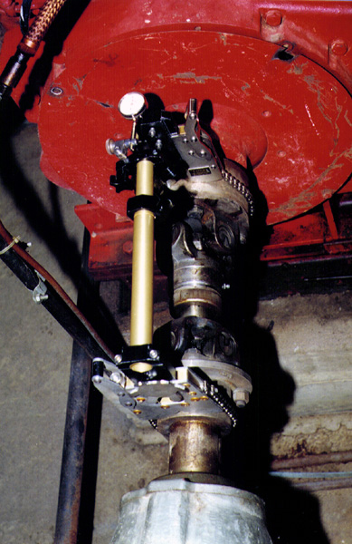
Here the brackets are capturing measurements across a universal joint drive.
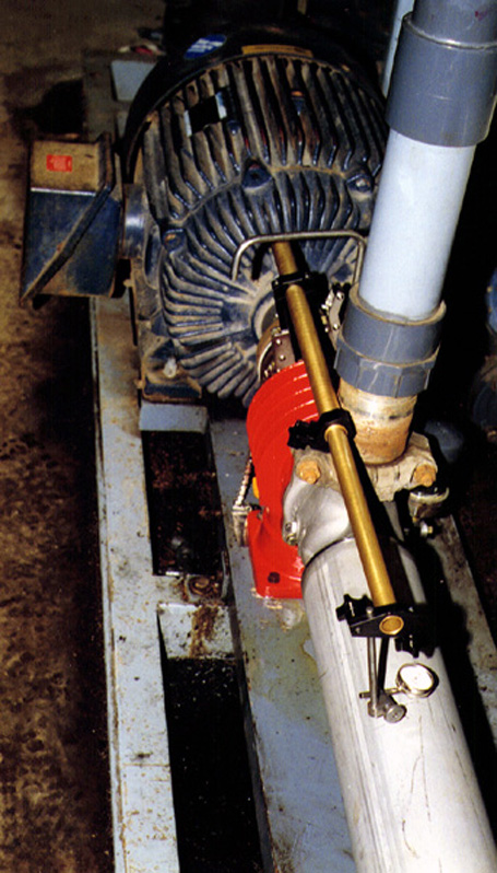
Here the bracket is attached to the pump shaft measuring whether the pump barrel is concentric with the pump shaft.
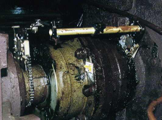
Dirt, grease, mud, water, freezing temperatures, blazing sun, or any environmental condition won't stop the measurement process.
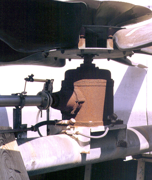
Here a bracket is attached to the input shaft of a cooling tower fan drive gearbox taking a measurement on the spool piece employing the shaft to coupling spool method.
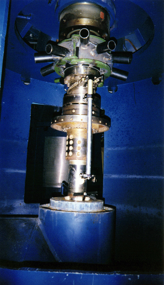
Here the bracket is attached to a 2500 hp motor driving a vertical pump. The dial indicator is capturing one set of measurments employing the double radial method.
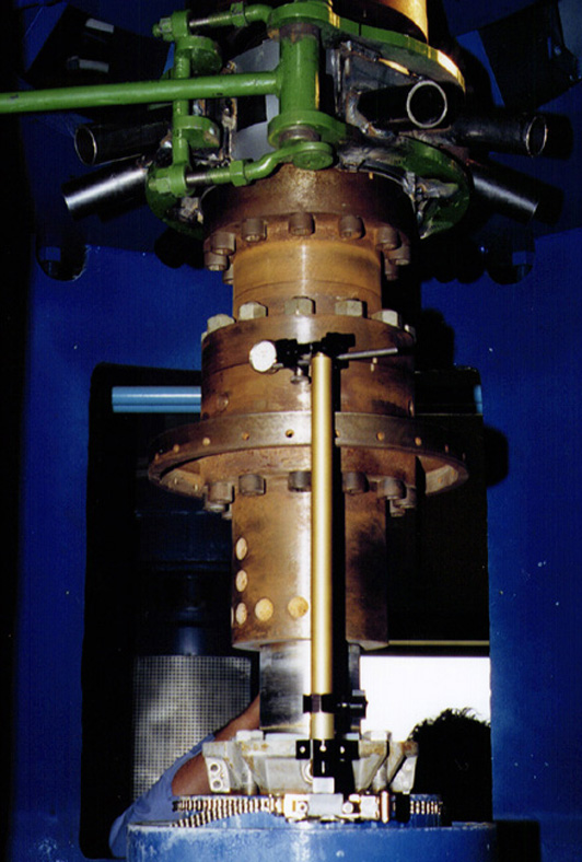
Here the bracket is clamped to the seal housing and the dial indicator is taking runout measurements. Yes, the bracket and indicator can be used for more than just alignment measurements!

Here, the bracket and indicator is capturing face measurements to insure that the fan shaft is perpendicular to the fan housing. Try to do that with another kind of alignment system!
